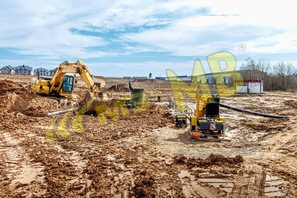
A few preliminary pointers and safety measures for any construction dewatering pump system setup. In this blog, we’ll discuss the construction dewatering methods & Pump tips. Here are some techniques, advice on which one to use, and some pointers for configuring them by the best dewatering pump manufacturers in India.
Wellpoint
Installing several wellpoints around an excavation is known as “wellpoint dewatering,” and it lowers the water table. Swing joints link the wellpoint to a header system, which in turn is connected to a wellpoint pump. In sandy environments, wellpoint dewatering methods function best. Typically, 6″ Sch 40 PVC header pipe and 1 ½” Sch 40 PVC wellpoints are used in Central Florida. Larger header pipes and wellpoints might be needed in other locations.
The wellpoint is a PVC pipe that is roughly the size of a business card, with the bottom three feet slotted at.010″. A wellpoint may typically dewater an area between 15 and 20 feet in diameter, depending on the properties of the soil. The excavation depth determines the wellpoint installation depth.
Installing the wellpoints five to six feet below the intended excavation depth is the general rule of thumb. To prevent silting or clogging, a filter medium made of rock, shell, or sand must be used while installing wellpoints. What kind of installation is needed will depend on the type of soil.
Hand installation is possible in healthy soil with a blow count of N value 10 or lower. The process of hand installation usually involves the use of a jet pump to force water at high pressure into a manually driven jet rod, usually measuring between 1 ½” and 2″ in diameter, which is then buried at the appropriate depth. The jet rod is taken out once the required depth is attained.
After inserting the wellpoint into the hole, filter media is placed around it. In soils with higher clay or rock content, a punch or drill is employed. Except for using a wellpoint punch in place of a jet rod, the punched method is comparable to the hand-installed approach. An excavator or other large piece of equipment is used to operate a wellpoint punch, which is larger (usually 2″ to 4″).
To achieve the required depth, a wet-drilled wellpoint system uses specially designed auger drills and water jets. The same auger is used in a dry-drilled system without water. This technique is well-liked in areas where soil pollution occurs. Cased well points are used in very poor soil conditions and require a specially designed punch (usually 6″ in diameter, but it can go up to 12″). After the punch reaches the proper level, sand and a wellpoint are added inside the punch to form a massive sand column that lets water seep through unsatisfactory soils. The most effective dewatering system uses a Rotary Wellpoint pump, regardless of the wellpoint installation technique used.
Deep Wells
Deep wells are wells installed to a depth of 25 to 50 feet that have a diameter of 6 inches or greater with slotted casings. To force the water up the wells and into a manifold header system, these require electric submersible pumps. Deep excavations are the primary usage for this expensive equipment.
Sock Dewatering
In sandy circumstances, sock dewatering is the best dewatering technique for ponds and lengthy pipe runs. A specialised trencher is used in “sock dewatering,” inserting a 6″ sock up to an 18″ depth. The sock is made of flexible corrugated pipe with a fine mesh covering surrounding a few tiny holes. This keeps additional detritus out of the sock while allowing groundwater to enter.
When employing a sock, the appropriate depth (about five feet below the excavation) is reached by installing a 6-inch corrugated sock header pipe at the start of the sock run, without any perforations. The intended run (a few hundred to several thousand feet) is marked on the perforated sock. To bring the line back up to grade, another 6-inch corrugated sock header pipe is used at the end of the run.
By allowing the sock to dewater to the required depth, these sock header pipes keep the pump from catching air and losing the vacuum until the groundwater is below the specified depth. A 20–30 foot radius can be dewatered with a sock dewatering device, depending on the soil’s properties. Sock dewatering has the advantage of not requiring an above-ground pipe. Beneath the excavation lies everything to save the system’s beginning and end. Utility conflicts in the ground must not exist for this strategy to work.
Here are some more pointers to consider while selecting the appropriate dewatering technique for a building project:
- Once a dewatering technique is selected, a pump vacuum is essential for effective operation.
- For any system to work correctly, it needs to be airtight.
- Generally speaking, one inch of vacuum is required to elevate one foot of water.
- When utilising a hydraulic pump, the vacuum won’t be a problem since the pump is positioned at the bottom of the excavation and forces the water to the top.
- If your lift is higher than twenty-five feet, hydraulic pumps are needed.
If the right dewatering technique is selected for the given situation, all of these approaches have been demonstrated to work. For more information contact dewatering pump manufacturers & suppliers in India.
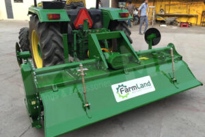
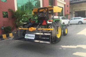
Read more about the Rotavator: Assembly, Application, Maintenance, and Safety Guidelines.